SP4T Control
The SP4T web UI shows a four-position control card mirroring the on-device
touch UI's 2x2 grid, backed by /api/sp4t.
Control Card
The card renders RF0–RF3 buttons above the state diagram. The active route's button is green and the diagram shows the corresponding routed path; the other three throws are drawn 50 Ω terminated.
The frontend selects the card from the canonical hardware_type field of
/api/system/status rather than substring-matching
model strings: SP4T renders the four-position card, SPDT the two-position
card, and ATTEN the attenuator controls.
State Diagrams
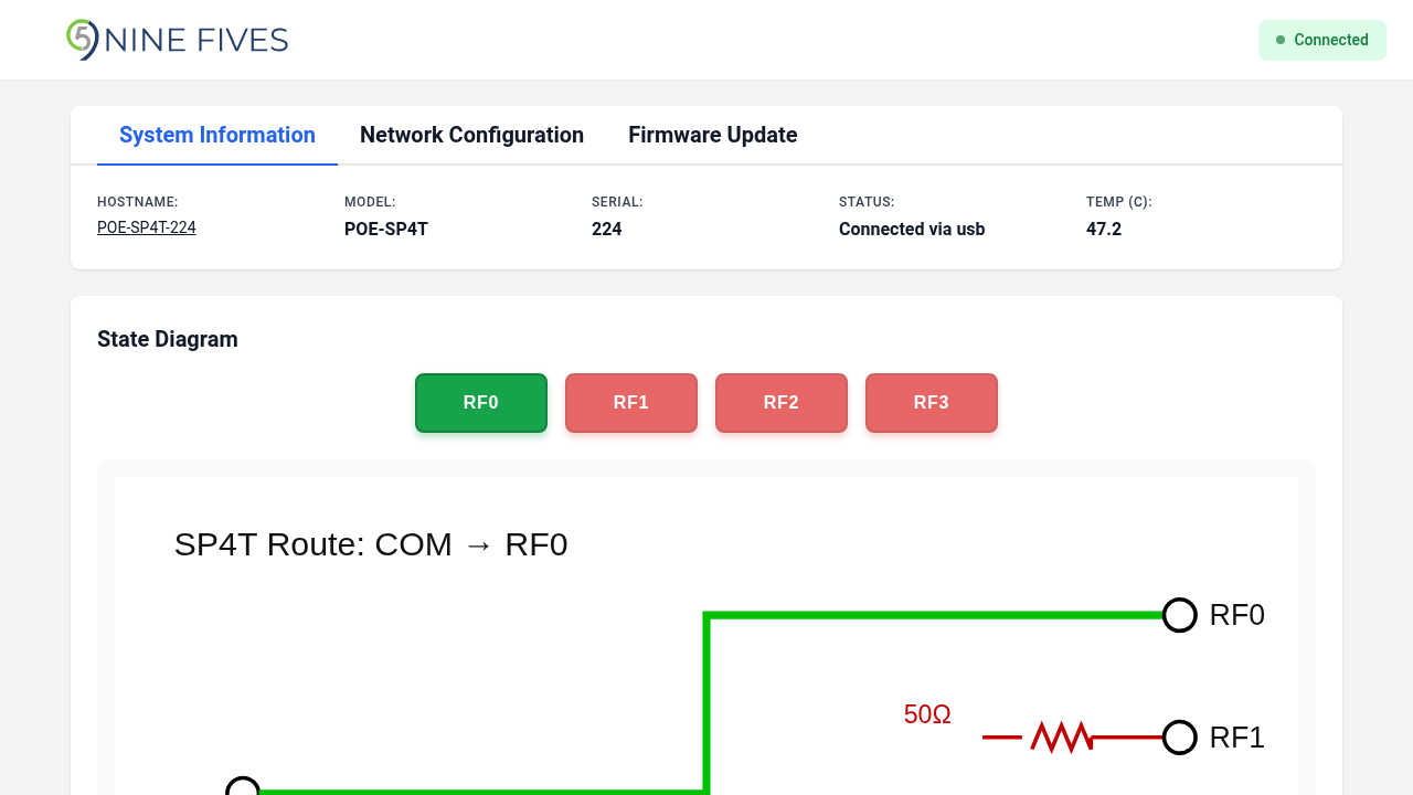
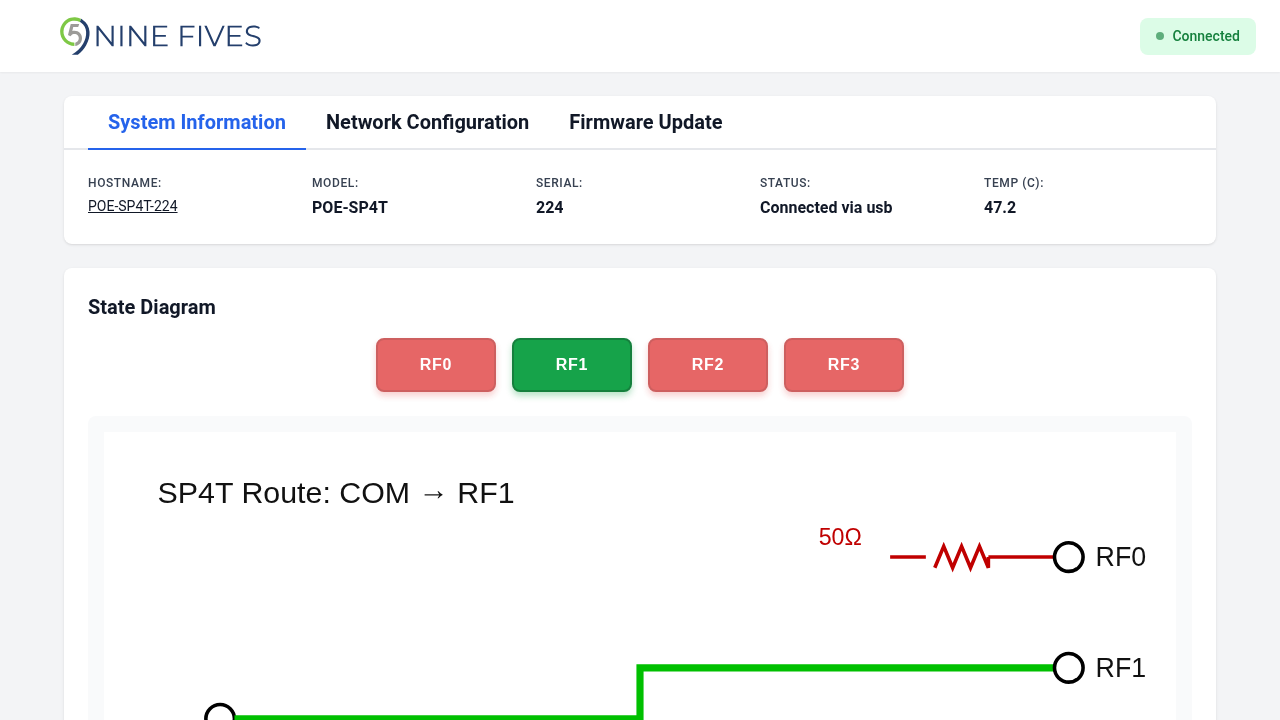
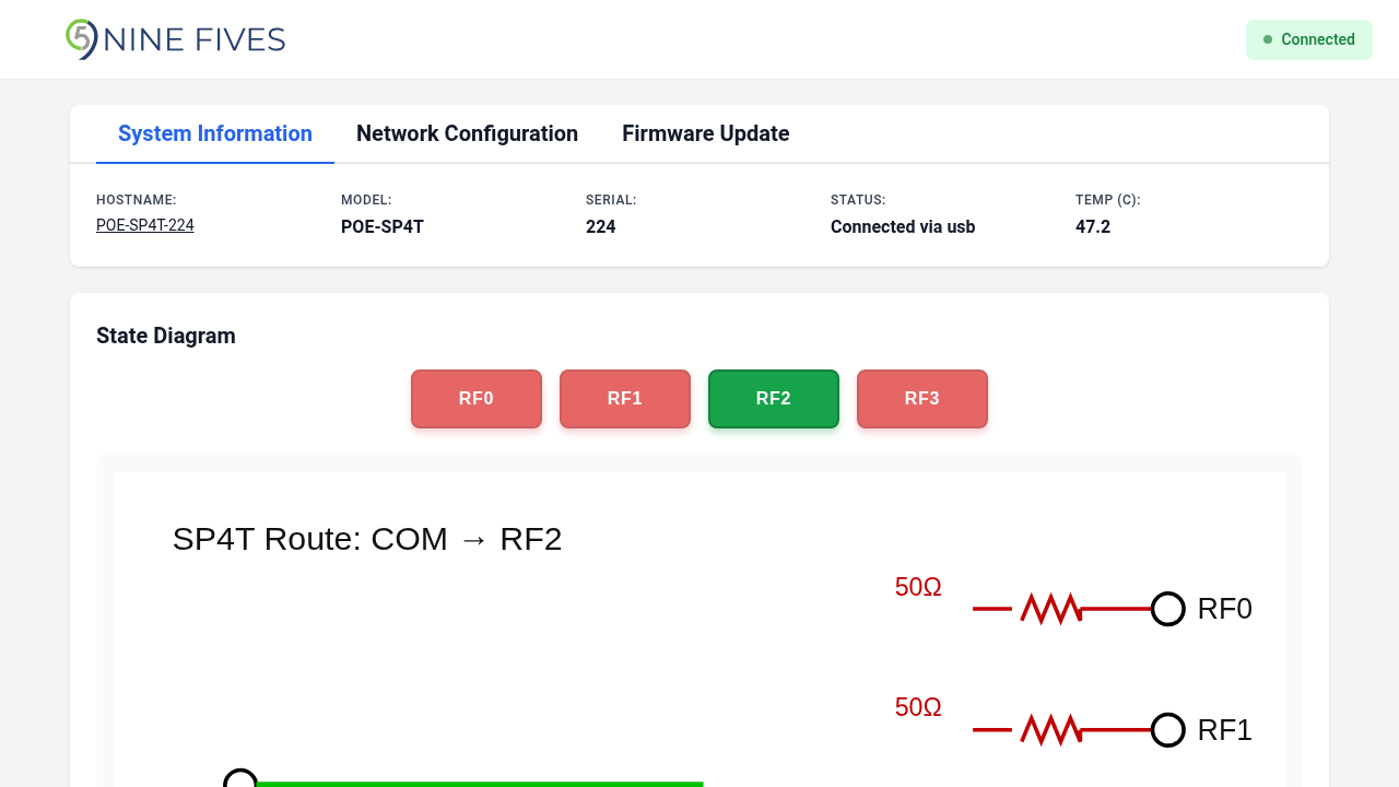
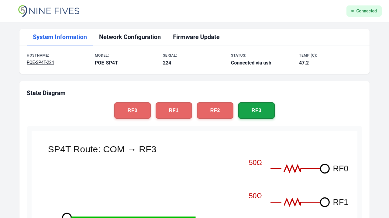
Four SVG diagrams (poe_sp4t.rf0.svg … poe_sp4t.rf3.svg) show the route for
each throw:
| State | Diagram |
|---|---|
| RF0 | COM → RF0 |
| RF1 | COM → RF1 |
| RF2 | COM → RF2 |
| RF3 | COM → RF3 |
Hardware Type Unset / Unknown
When hardware_type is unset or unknown, the runtime starts no RF manager
and the web UI renders a disabled-hardware card instead of any control card.
Network configuration remains available from the Network Configuration tab.
Provisioning
SP4T boards must have get_nf_part_variant.sh return SP4T. A board left
as SWITCH runs as SPDT, never requests EXT_GPIO1, and leaves the route
indeterminate in whichever half the undriven line selects — the runtime
startup log is the only signal.
See SPDT Control for the two-position variant.