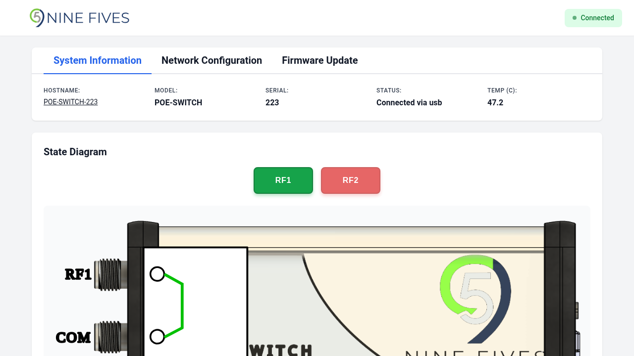
Switch Control
The State Diagram card provides direct control over the RF switch position.

Controls
Two buttons select the active switch position:
| Button | Description |
|---|---|
| RF0 | Routes the signal through RF port 0 |
| RF1 | Routes the signal through RF port 1 |
The active position button is highlighted. Both buttons are disabled when the device is disconnected.
State Diagram
A diagram below the buttons shows the current signal routing path, updating in real time when the switch position changes.